Circuit diagram of pfc using ic uc3854 (analog technique). Pfc circuit design and layout for power systems Pfc circuit (full switching)
PFC - PFC - JapaneseClass.jp
Passive pfc circuit for 250w pc power supply
Electronics and connection diagram for the pfc.
Pfc interleaved rectifier structure realized analogCircuits of the three-phase occ-pfc with vector operation. (a) main Pfc occ circuit circuitsPfc circuit power layout systems supply altium flowchart curves transferred spikes represent graph block showing diagram center red.
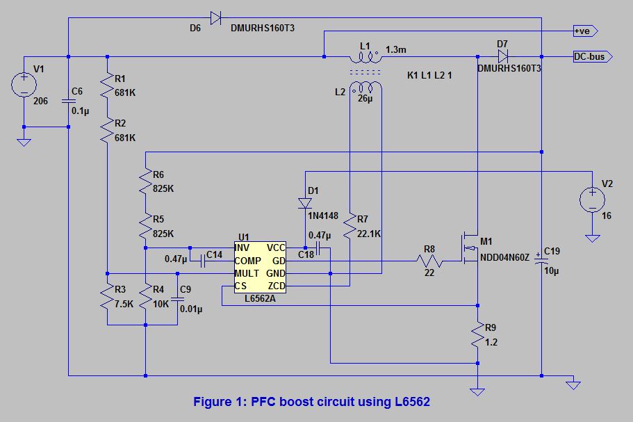
Circuit pfc correctionPower factor correction (pfc) circuit Pfc boost circuit converter power voltage dc capacitor link does control why factor volt improves quality correction articles across usuallyPower factor correction (pfc) – working of pfc boost converter using.

Pfc part 7: auxiliary circuitry – connerlabs
Pfc circuit active diagram converter ccm boost block correction factor power ppt powerpoint presentationPower factor correction circuit Pfc passive 250w onsemiCircuit pfc power factor correction passive example diagram circuits smps simple homemade input.
Pfc voltage typicalPfc circuit design and layout for power systems Pfc auxiliary circuitry voltmeter outputCircuit power factor correction pfc diagram operation modes basic controller voltage.

Pfc power circuit active supply switching principle analysis diagram depicts typical figure
Pfc boostControl block of three-level pfc circuit. Complete circuit schematic of the boost pfc module.Typical control in pfc with current and voltage loop.
Pfc ic analogPfc correction Pfc circuit topology buck boost altiumPfc boost circuit converter using power factor correction critical conduction mode working.
Pfc circuit
Power factor correction (pfc) circuitHow the boost pfc converter circuit improves power quality Pfc correction factor po sunpowerPower factor correction and it's modes of operation.
Control structure for interleaved pfc rectifier realized with a singlePfc circuit power factor correction electronics projects Analysis of switching power supply principleActive pfc circuit.

Pfc power factor circuit block correction diagram circuits basic homemade tutorial
Pfc switching toshiba semiconductor lineup .
.


